A year of building a 3D bioprinter
Published:
For the past year a team of ten of us has been building a 3D bioprinter during our undergrad. I lead the project. It’s called BioP, it swaps a desktop printer’s plastic filament for soft gels, and it has taught me more engineering than every course I’ve taken combined. This post is an account of what building it involves, with the numbers.
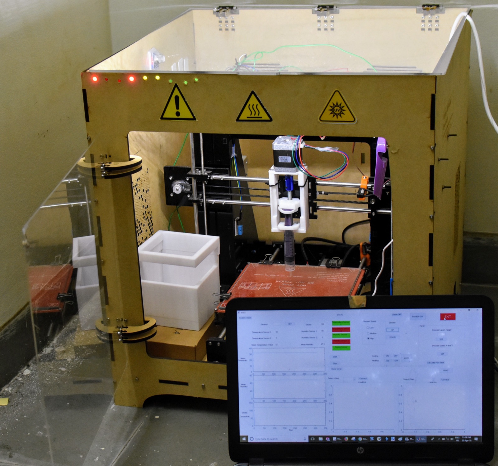
This is the machine. The motion platform started as a Prusa i3-class frame from the RepRap family, and almost everything above the bed has since been replaced: the extruder, the enclosure, the electronics, and all of the software. The warning stickers on the front are there because the enclosure has a UV curing lamp and a heated bed, and both can hurt you.
The project has picked up awards along the way, including selection as a World Summit Award Young Innovators winner. Most of the year, though, has looked like the work below.
A normal desktop 3D printer is a solved problem. The RepRap lineage worked out thermoplastics years ago: melt a filament, push it through a hot nozzle, and the plastic freezes where you put it. Plastic is a forgiving material, so the control loop can be simple.
Bioprinting replaces that plastic with hydrogels, soft water-based materials that living cells can survive in. We work with alginate crosslinked with calcium, with Laponite, and with GelMA, a gelatin derivative that cures under UV. Each one is a compromise between printing well and being worth printing. The gels that hold shape best are the ones cells survive worst in.
The rheology
Hydrogels flow when pushed and stiffen when still, a property called shear thinning, and the balance between pressure, temperature, and speed decides whether a print holds its shape or collapses into a puddle. The window where everything works is narrow, it moves with room temperature, and it’s different for every ink batch.
The proper name for the physics is a yield-stress fluid. Below a threshold stress the ink behaves like a solid, above it like a liquid, and printing happens right at the crossing. Our alginate and Laponite blend yields at around 60 Pa on the rheometer, which is what lets a printed line sit on the plate without spreading and still flow through a needle under pressure.
Inside the needle the numbers get large quickly. The shear rate at the wall of a tube is about 4Q / (π r³). A 22G needle has a 0.41 mm bore, and at 10 µL/s that comes to roughly 1,500 s⁻¹, and more for a shear-thinning ink. Hagen-Poiseuille scaling puts driving pressure against the fourth power of radius, so one step down in needle gauge multiplies the pressure several times and the shear at the wall climbs with it.
That shear is the constraint that matters, because the same forces that make the ink flow are the ones that tear living cells apart. The wall shear stress is τ_w = ΔP r / (2L), pressure drop times needle radius over twice the needle length. At 40 psi through a 12.7 mm long 22G needle that’s about 2.2 kPa. The literature puts the viability cliff for most cell types in the low single-digit kilopascals, so 40 psi on a 22G is about as hard as we push, and a finer needle at the same flow would push past it. The point of a bioprinter is that the cells arrive alive.
So the daily work is sweeping parameters and writing the results on the plate in marker, so the notes stay with the sample.
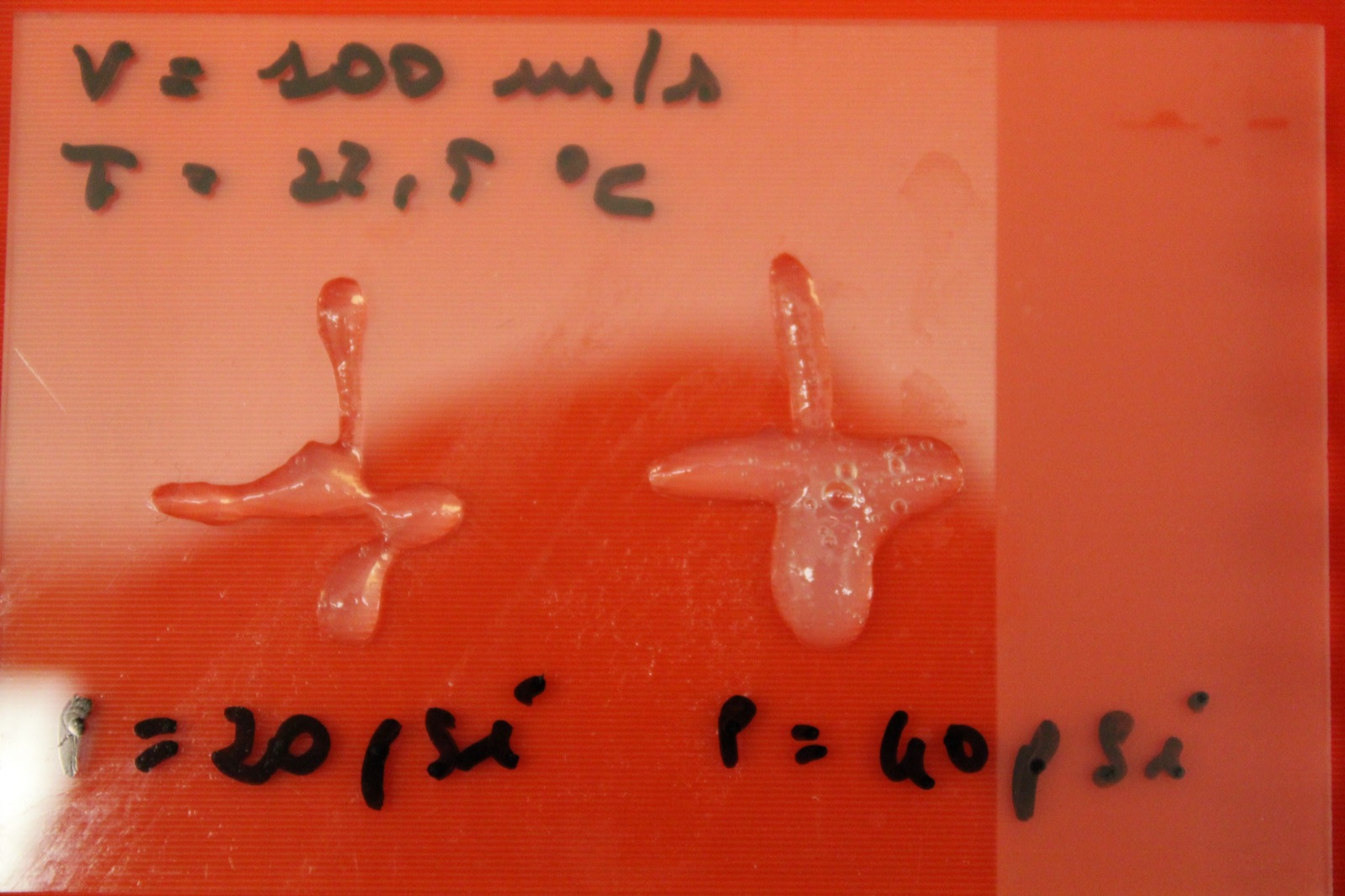
The G-code for both of these prints describes a clean cross. At 20 psi the ink under-extrudes and the arms thin out. At 40 psi it swells past the toolpath and pools at the junction. Same geometry file, same nozzle, same day.
Curing
A printed shape only holds if it sets. Alginate crosslinks ionically wherever calcium ions reach it, so those prints get misted with 2% calcium chloride and stiffen from the outside in. GelMA cures under the UV lamp through a photoinitiator mixed into the ink, Irgacure 2959 at 0.5% w/v in a 5% GelMA solution in our case, and the dose is its own parameter. The lamp puts about 10 mW/cm² of 365 nm light onto the bed, and 60 seconds per layer gives a dose of 600 mJ/cm², which is where our stiffness stopped improving. Under-cured layers slump before the next pass lands, over-cured ones go brittle, and the lamp’s heat dries the print while it works. The very top of each layer stays slightly tacky because air stops the reaction at the surface, and that helps the next layer bond. Each layer has to set before the next one lands on it, and the UV timing decides whether it does.
Two toolheads
The machine carries two ways of moving ink. A pneumatic head runs a syringe off a regulated air line through a solenoid valve, and that’s what the 20 and 40 psi sweeps use. It’s the right tool for low-viscosity inks and for GelMA, which needs to stay warm and flows easily. The mechanical head is a syringe pump we designed ourselves, and it’s what the pastes need, because a shear-thinning ink under constant pressure flows at a rate that depends on its yield stress that day, while a displacement pump moves the volume you asked for regardless.
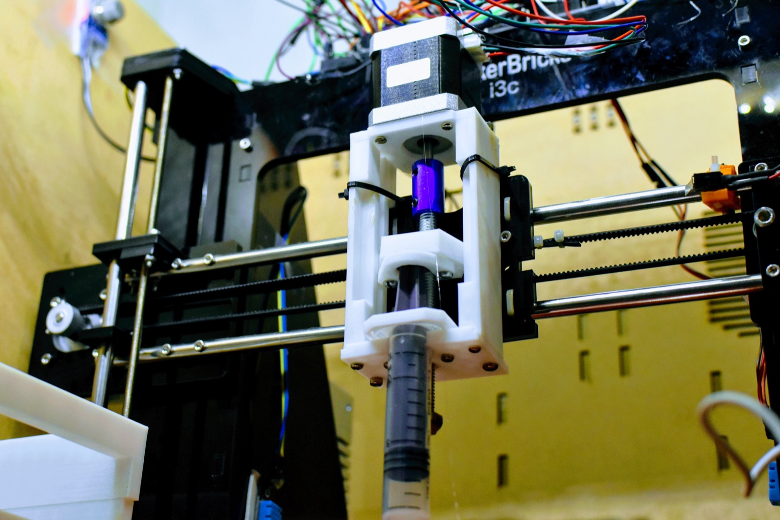
The pump is a stepper-driven carriage that presses a standard syringe through a leadscrew, printed in parts on the same class of machine it now improves. This is where most of the design iterations went. Too much backlash and the ink keeps flowing after the move ends. Too much friction and the stepper skips exactly one step, which you discover three layers later.
The arithmetic is volumetric. The leadscrew has a 2 mm lead and the motor runs at 3,200 microsteps per turn, so one microstep moves the plunger 0.625 µm. In a 1 mL syringe that’s about 11 nL of ink per microstep. A printed line 0.4 mm wide and 0.3 mm tall needs 0.12 µL per millimetre, so about 11 microsteps per millimetre of line. A 5 mL syringe pushes six times the volume per microstep, and the resolution falls to under two microsteps per millimetre, which is why the fine work runs from the small syringe. The nozzle is a blunt dispensing needle on a Luer fitting, sized in gauge like anything in a clinic.
The syringe also behaves like a spring. Seals flex and the gel compresses, so flow lags the command at both ends of a move. The plunger retracts 2 mm before every travel move to relieve the pressure and fight the ooze, and re-primes the same 2 mm before the next line. The flow still stops a little after you tell it to.
Here is fourteen seconds of it printing into a dish under the UV lamp:
Motion control
Everything moves on stepper motors, and steppers shape the whole machine because they’re open loop. No encoder reports where an axis is. The controller counts microsteps and trusts dead reckoning. Demand too much acceleration and a motor skips silently, and the position count is wrong from then on.
The numbers: A4988 drivers at 1/16 microstepping. X and Y run on GT2 belts over 20-tooth pulleys, so one revolution is 40 mm and the steps-per-millimetre is 3,200 / 40 = 80. Z runs on a T8 leadscrew with an 8 mm lead, 3,200 / 8 = 400 steps/mm. The firmware is Marlin-derived, and its planner runs every move as a trapezoid: accelerate at 500 mm/s², cruise, decelerate, with corners taken slowly because every corner is where the ink pools. Coordinated motion is Bresenham’s line algorithm running on step pulses inside a timer interrupt, the same arithmetic that draws pixels on a screen. Every session starts by driving each axis into its limit switch at 5 mm/s, because the home switches are the only position reference the machine has.
The other routine is calibration. Steps-per-millimetre on each axis gets checked with calipers against a commanded 100 mm move, and the difference between repeatability and accuracy matters here. A gantry that lands 0.1 mm off the same way every time can be fixed in software. One that lands somewhere new each pass is scrap. With a dial gauge on the carriage, ours repeats to about 0.05 mm on X and Y. First layers get trammed with a sheet of paper under the needle, same as any other 3D printer.
Electronics
Motion and extrusion run on Arduino-based control. We wrote the firmware, built a G-code conversion path for our toolhead, and rebuilt both more times than I want to count.
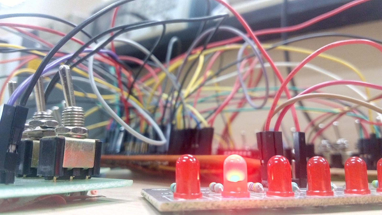
This photo is what prototyping hardware looks like. The schematic in the design file is clean. The bench isn’t, because each extra wire in that tangle is there to check something the schematic didn’t cover: whether the endstop chatters, or whether the pressure line leaks mid-print.
In software you recompile and the old mistake is gone. In hardware a stripped thread and a burnt driver stay that way, and the print that failed at 2 a.m. used real ink from a batch that took a day to prepare. Debugging with a multimeter costs hours where debugging with a print statement costs seconds.
Control software
Slicers assume filament, so we wrote our own control software, BioApp. It runs the printer over serial: jog controls, layer height, speed, a print-time calculator, and a start button we trust because we know exactly what it does.
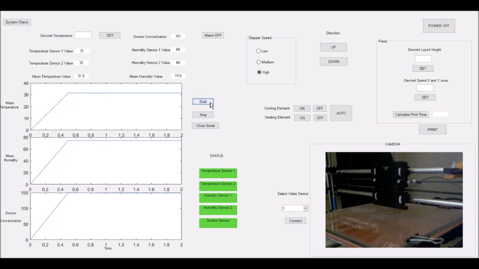
Half the interface is environment monitoring, because hydrogel prints are sensitive to the room. Two temperature sensors and two humidity sensors feed running means, a smoke sensor watches the electronics with an alarm wired to it, and a camera points at the bed so a print can be watched from across the lab. We print at 22.5 °C and around 60% relative humidity, and the log shows why: at 30% humidity an alginate line loses a visible fraction of its width to evaporation before the next layer lands.
Layer height correction with a camera
Bioprinting has a control problem that plastic printing mostly ignores. The G-code assumes every layer lands exactly one layer-height tall, so the nozzle climbs by a fixed step per layer, open loop. Hydrogels break that assumption from both directions. Ink swells as it leaves the nozzle, a rheology effect called die swell, and then slumps as it settles before curing. The error per layer is small and it compounds, so by layer twenty the nozzle is either ploughing through the print or extruding into air.
The fix is to measure the layer and correct for it. A camera looking straight down can’t see height, so the bed camera sits at a low angle and a cheap line laser stripes the bed from the other side, the same triangulation the scanner used. After camera calibration, a checkerboard on the bed gives the homography from pixels to bed millimetres, and the sideways displacement of the laser stripe where it crosses the last pass gives its height. OpenCV thresholding and Canny edges find the stripe. At our geometry a pixel is a few hundredths of a millimetre of height.
A closed-loop controller then decides the next layer’s Z:
z[k+1] = z[k] + h_nominal + K * (h_measured - h_nominal)
with K = 0.4 and the correction clamped to ±0.1 mm per layer. The error dynamics are e[k+1] = (1 − K) e[k], so a height error decays to 8% of itself over five layers. Push K past one and (1 − K) goes negative: the correction overshoots, and the machine oscillates between too high and too low on alternate layers. Each layer gets measured, and the next layer’s Z is adjusted to match.
Right now it works on opaque inks in good light. A wet transparent gel under a UV lamp is a bad computer-vision subject, all glare and low contrast, and the classical pipeline needs re-tuning for every new ink. That’s most of what I’ve been reading about lately.
CAD
The full enclosure, rendered as a turntable from the design files, from back when rendering it was easier than building it:
What I learned
- Change one variable per print. A plate with two changed variables teaches nothing, and the grid grows faster than the ink budget.
- Write the parameters on the plate, photograph the plate, file the photo. You won’t remember.
- The material sets the limits. Wall shear stress at the needle, τ_w = ΔP r / 2L, is the number that decides whether cells survive, and no control loop moves it.
- Cheap components are expensive. Every rupee saved on a stepper driver was paid back in debugging evenings, with interest.
- If the machine can measure something, stop assuming it. We assumed layer height for months, and the laser measurement showed we were wrong.
- When a print fails, trust the print over the plan. The G-code, the firmware, and the datasheet all say what should have happened. The failed print says what did.
- A ten-person build runs on writing things down. A design that lives in one head is a single point of failure, and that person has exams.
A semester of thesis work in a bioprinting lab in Boston taught me the formal versions of these rules. Building our own machine from scratch taught me why they exist.
Next
The part of this work I keep drifting toward is the imaging side. Checking a printed structure means imaging it, and reconstructing useful 3D information from those images is its own problem. I’ve started working with machine learning for image reconstruction there, and it’s the most interesting thing I’ve touched in months. The models find structure in data I would have called noise.
The printer isn’t finished. Printers like this never are. But it prints, the ink does what we expect more often than it used to, and the folder of plate photos keeps growing.
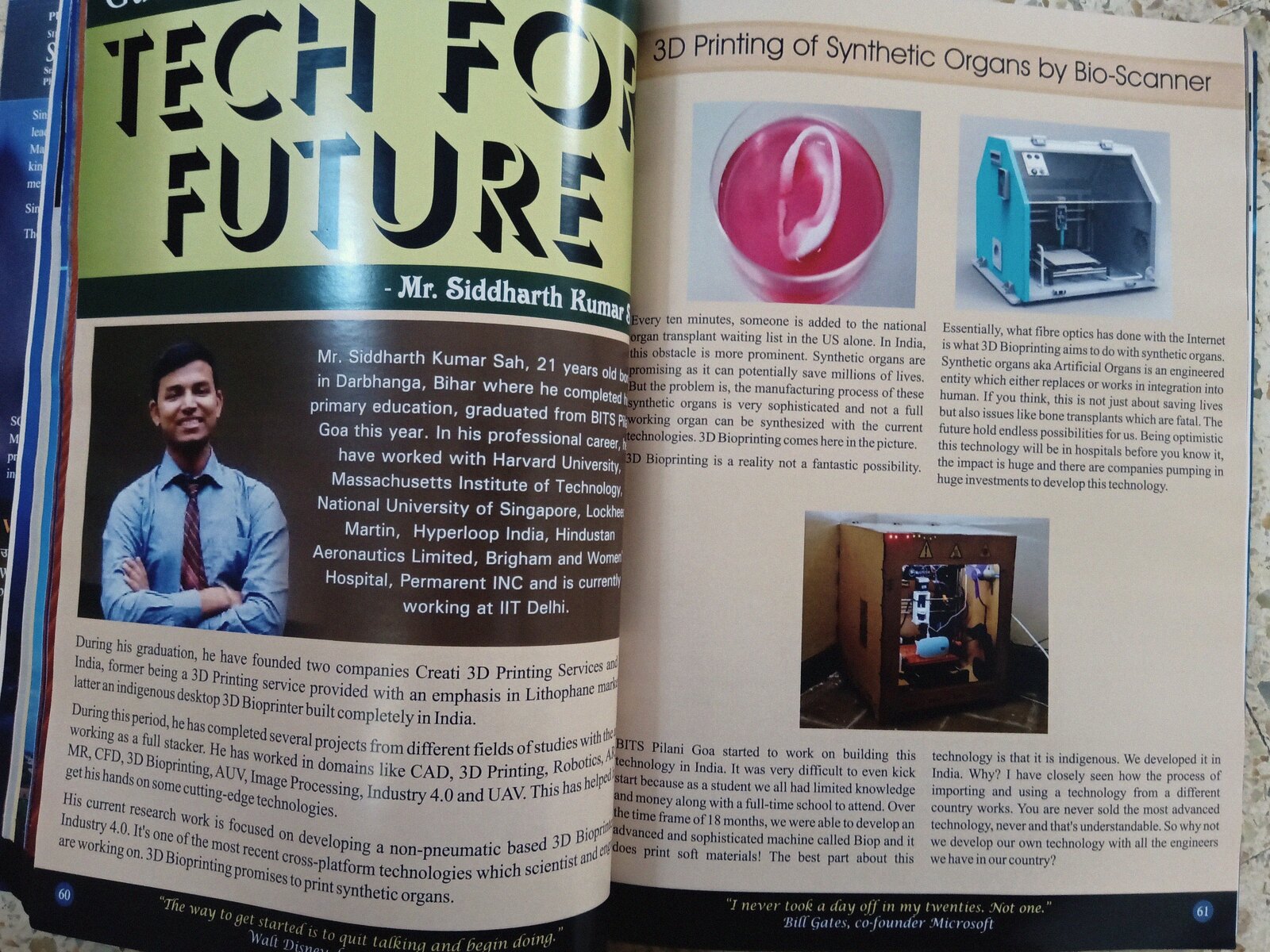
Update, September 2019. BioP made it into print. A magazine ran a spread on the machine and the synthetic-organ case, the CAD render next to a photo of the real enclosure.