
Three years of RC planes and multirotors
Published:
For the past three years most of my pocket money has gone into foam. Foam board, thermocol sheet, hot glue, cheap servos, and propellers bought in fives because they break in fours. This is a look back at the aircraft years, with the numbers behind the builds, written while the last of the fleet still hangs from the hostel ceiling.
We learned from Flite Test. Their free plans and build videos were the textbook: print the tiled PDF, glue it to foam board, cut, fold, add a cheap brushless motor, and you have an airplane. The archive on my drive is in the order we built them: the FT Cruiser, the Nutball (a flying disc that flies better than it looks like it should), the Mini Guinea we built for carrying payloads, and a folder of fighter-jet plans we couldn’t afford the batteries for.
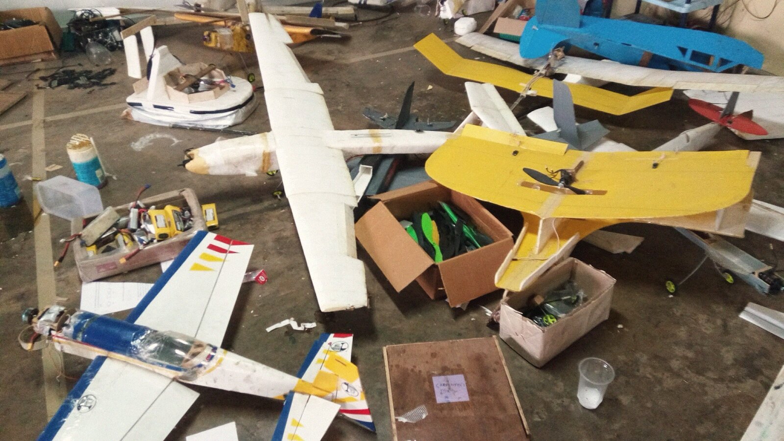
By the third year the workshop was full. Wings leaned against every wall, a hovercraft sat where furniture should be, and one trainer flew with a soft-drink bottle for a fuselage because the bottle was the right diameter and free.
Scratch building
After a few copies we started designing our own. This one is ours from nose to tail:
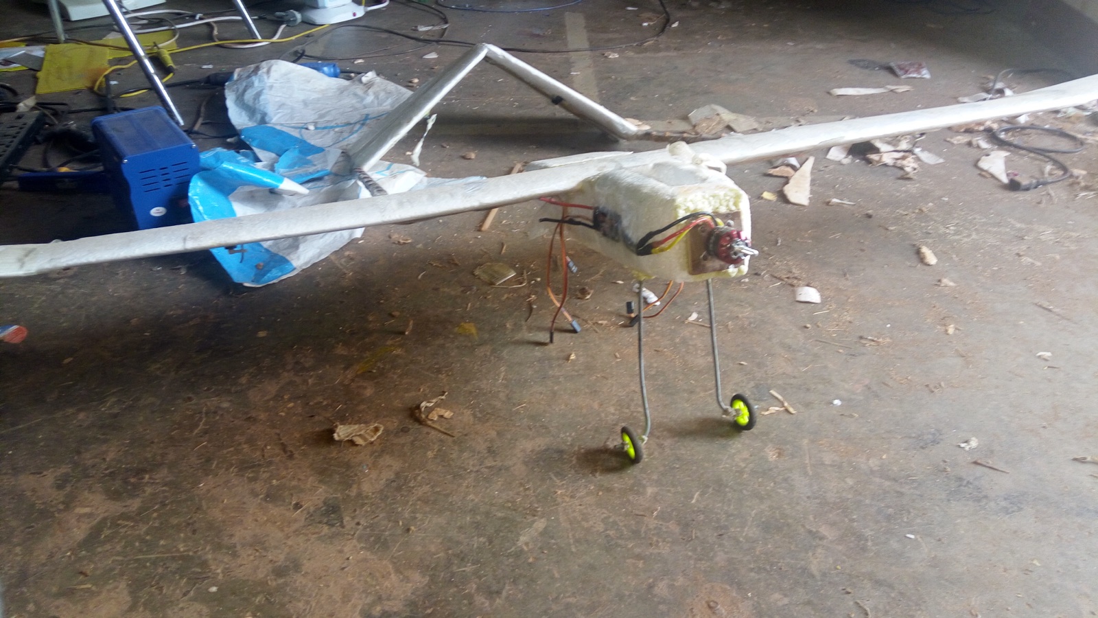
Each part in that photo has a reason. The wing sits high with generous dihedral because a trainer should roll itself level when the pilot panics. The landing gear is bent steel wire because anything stiffer breaks on a grass field. The airframe is thermocol because a crash should cost twenty rupees of material.
The numbers on that trainer: 550 g all up, 1,000 mm span, 220 mm chord, so 22 dm² of wing and a wing loading of 25 g/dm². Stall speed is V = sqrt(2W / (ρ S C_Lmax)). With a flat-plate foam section good for a C_Lmax of about 1.2, that’s sqrt(2 × 5.4 N / (1.2 kg/m³ × 0.22 m² × 1.2)) ≈ 5.8 m/s. It settles onto the grass at a fast walk, and a bad landing at that speed bends the wire gear and nothing else.
Once the copies flew, the designs drifted. This one has no tail at all:
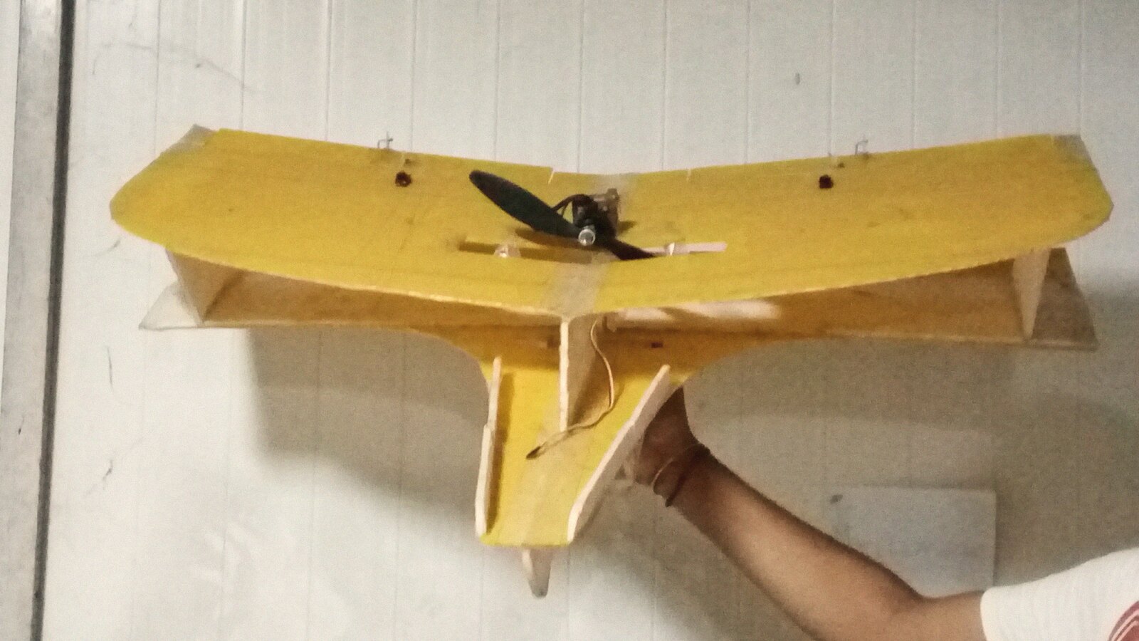
A flying wing steers with two elevons that mix pitch and roll into the same pair of surfaces. Sweep stands in for the missing stabilizer, and the motor rides in a cutout in the wing itself. Without a tail there’s nothing to hold the nose up, so the airfoil needs reflex, a trailing edge bent slightly upward, to give the wing its own nose-up pitching moment. The balance point sits at about 20% of the mean aerodynamic chord. The elevon mix is two lines in the transmitter: left = pitch + roll, right = pitch − roll. The whole aircraft is a few sheets of foam board and one argument about where the balance point goes.
The most ambitious scratch design got a name. Blue Thunder is a biplane built for steady, slow aerial filming. Two stacked wings give low wing loading at a short span. The cost is that the wings interfere with each other’s airflow, and positive stagger, the upper wing shifted forward, reduces that. We ran a gap of about one chord between the wings, with the top one a little forward. The upper airfoil is symmetric and the lower one is a flat-bottomed lifting section pressed into camber over a wooden spar. Two carbon rods stiffen the top wing, bicycle spokes serve as pushrods, and an 1100 KV motor swings a 10x4.7 propeller on a 3S pack. KV times voltage gives about 12,000 rpm no-load on 11.1 V, closer to 10,000 under the prop, and 10,000 rpm times 4.7 inches of pitch is a top speed of about 20 m/s. The motor pulls about 16 A, so 180 W, for roughly 900 g of static thrust. All up it weighs about a kilogram, carries a bay for a camera or a second battery, and we ran its polars through XFLR5 before cutting any foam.
Foam sheet is one way to build. The other is built-up construction: a truss fuselage of balsa sticks, plywood formers at the load points, a spar carrying the wing’s bending loads, and a skin that does little except keep the airflow attached. We tried that too:
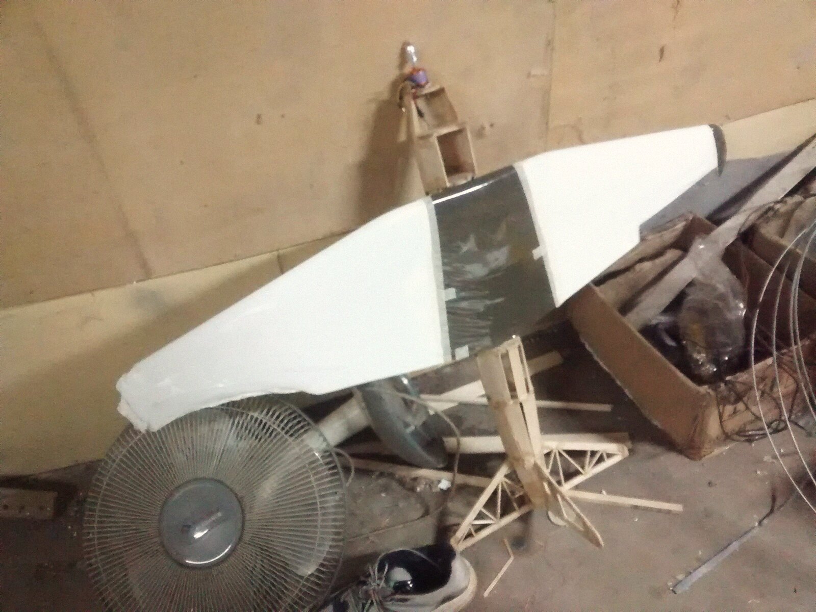
A truss makes the load paths visible. Every stick either carries something or gets cut, the structure weighs a fraction of a solid fuselage, and one bad landing turns a week of careful gluing back into sticks. The spar in that wing is an I-beam: balsa caps top and bottom taking the bending as tension and compression, a vertical-grain balsa shear web between them. Foam board is much easier to repair.
The balance point mattered more than anything else. The center of gravity has to sit ahead of the wing’s neutral point for the aircraft to have positive static stability. The distance between them, as a fraction of the chord, is the static margin, and we aimed for 10%: enough to recover from a stall by itself, still lively on the elevator. A bigger tail moves the neutral point aft and buys more margin, at the cost of drag. Every build ends with sliding a battery back and forth until the model balances on two fingertips at a quarter of the wing chord. The club saying is: a nose-heavy plane flies poorly, a tail-heavy plane flies once.
Flight testing
This is an October evening on the campus grounds, one of ours in the air and one of us running underneath it. Every maiden flight follows the same steps: range check, control throws, one deep breath, and a hand launch into whatever headwind exists. The first ten seconds show whether the trim is right. A mis-trimmed plane shows it immediately, and a stalled wing gives you about a second of warning at these speeds.
We crashed a lot. Each wreck traced back to something specific: a battery that shifted aft in flight, control throws too aggressive for a windy day, a launch below flying speed. Repairs were where we worked out what had gone wrong.
Multirotors
A multirotor is a different problem. A plane is stable on its own and the pilot mostly corrects. A multirotor is four motors that would fall out of the sky without a control board correcting them hundreds of times a second. On a quadcopter adjacent propellers spin in opposite directions so their reaction torques cancel, and yaw comes from speeding up one diagonal pair. The mixer is four lines:
front-left  = throttle + pitch + roll - yaw
front-right = throttle + pitch - roll + yaw
rear-left   = throttle - pitch + roll + yaw
rear-right  = throttle - pitch - roll - yaw
A tricopter cancels nothing, so its tail motor rides on a servo that tilts it, vectoring thrust to hold the nose where the pilot left it.
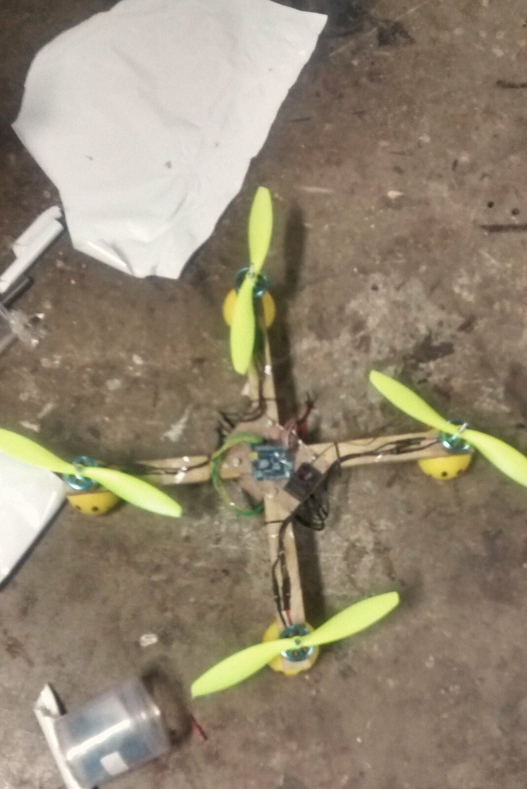
This is the first one, wooden arms and an Arduino wired in as the flight controller. It looks like a school project, and every frame we built afterward borrowed parts from it. The Arduino ran a MultiWii-style loop at about 400 Hz: read the gyro and accelerometer, blend them into an attitude estimate, run the PIDs, write four ESC pulses. The blend is a complementary filter, which trusts the gyro for fast motion and lets the accelerometer pull the drift back over a few seconds.
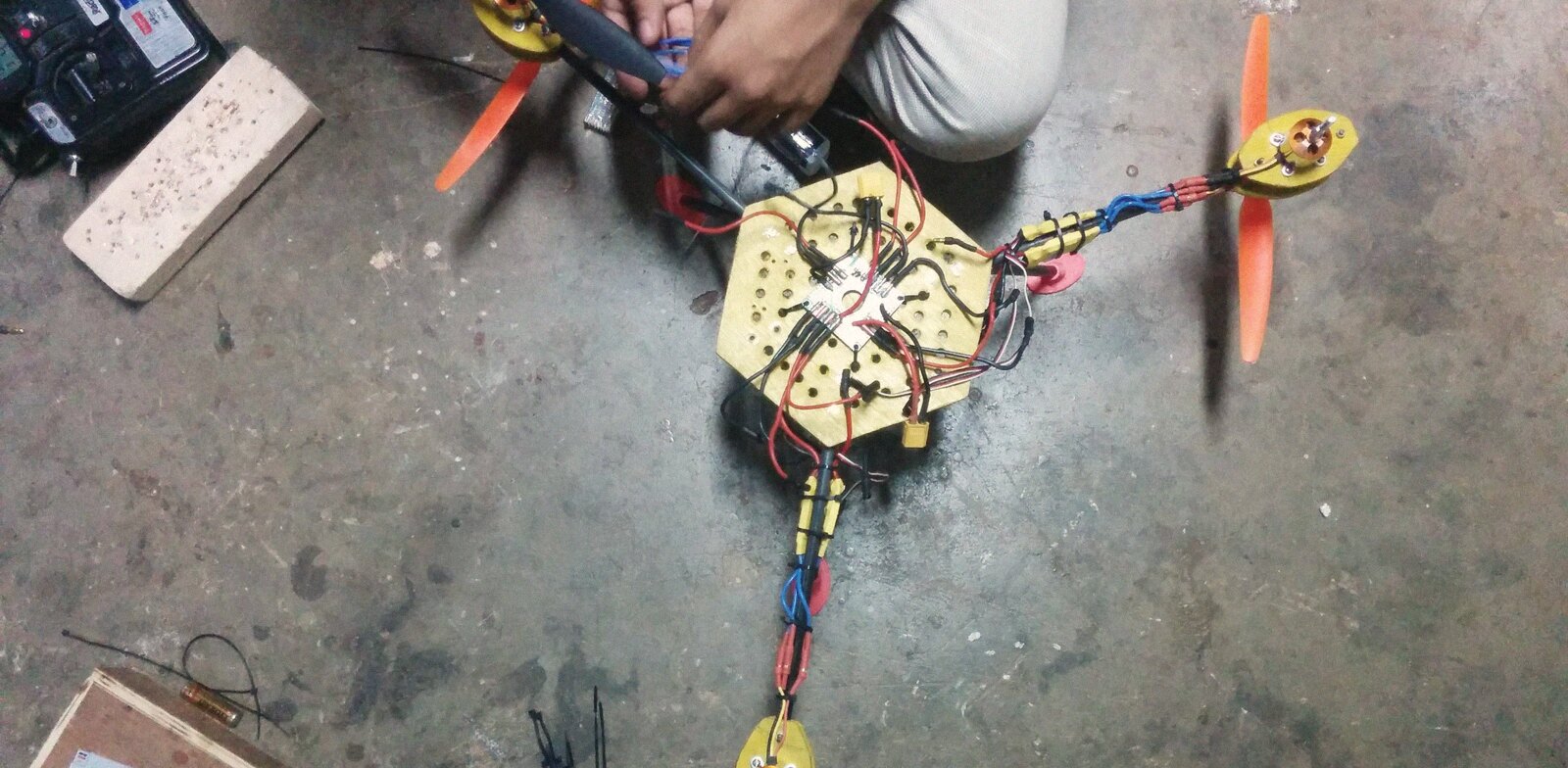
The build routine barely changed between frames. Calibrate every ESC so all the motors agree on what full throttle means. Balance every propeller, because the flight controller’s IMU reads vibration as motion, and an unbalanced prop at 8,000 rpm is a 133 Hz shake right in the frequency range the controller responds to. Mount the board on foam tape for the same reason. Then spend an evening on PID gains for the rate loop: raise the proportional term until the frame oscillates, back it off by a third, add derivative until the twitch smooths out, and hold off on the integral term until a breeze proves you need it.
The shrouds were our one deliberate aerodynamics experiment:
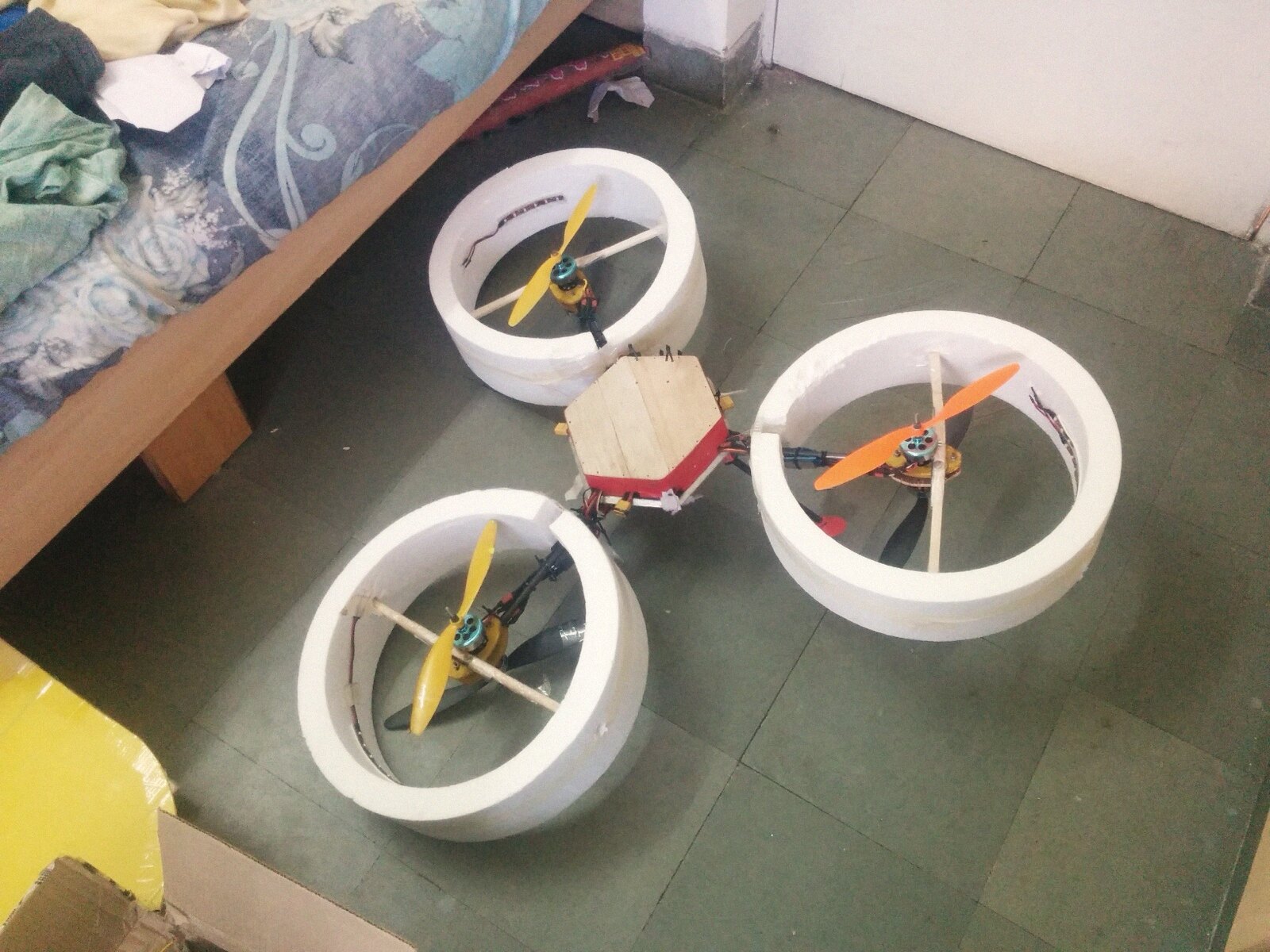
A duct around a rotor can add lift for free. It suppresses the tip vortex losses at the blade ends and, shaped well, pulls extra air through the disc for the same watts. The textbook number is up to about 25% more thrust for the same power from a well-made duct. The fine print is weight, drag in forward flight, and a tip gap that has to be around 1% of the rotor radius for the theory to hold. Ours, hand-cut from thermocol, had a 3 mm gap on a 100 mm radius, and the luggage-scale test showed no gain we could measure.
This is from a September evening:
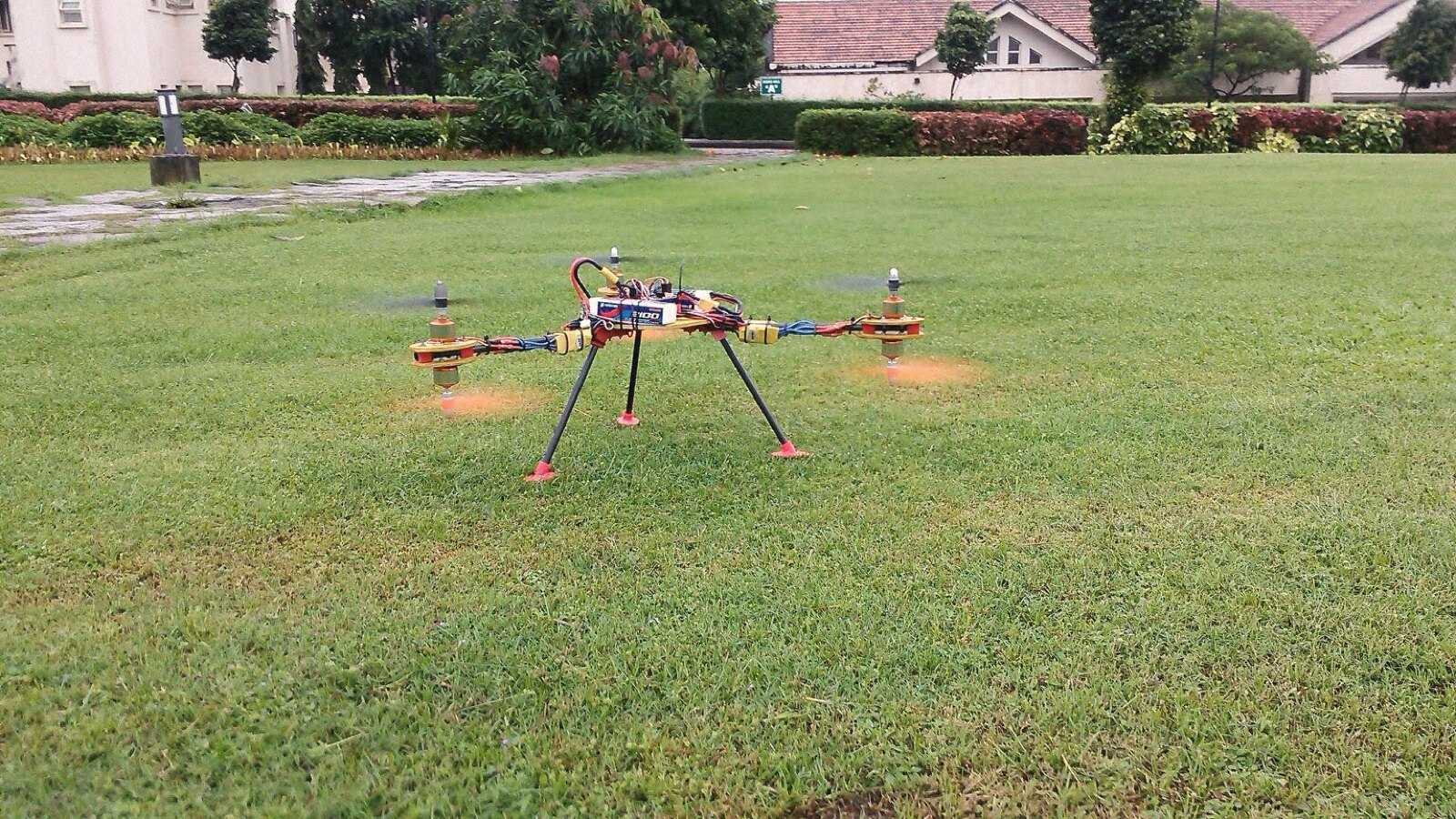
Props blurred, skids a hand’s width off the grass, football practice going on behind. A hover that steady means the PID gains are right.
The APM autopilot
The APM flight controller changed how we flew. We assembled a Y6, a coaxial hexacopter with its six motors stacked in pairs on three arms, around one running ArduPilot, configured it in Mission Planner, and got a flight-mode menu: stabilize, loiter, position, land. Loiter closes a position loop on GPS and barometer around the attitude loop we used to tune by hand, and it holds within a metre or two in a breeze. The FPV rig on it later grew a head tracker, so turning your head panned the camera. That’s the closest thing to sitting inside the aircraft this hobby offers. The first time loiter mode parked the hexacopter against a breeze, holding position better than any of us could by hand, the fixed-wing people in the club stopped arguing.
I keep thinking about that. Three years of practice, and a control loop with an IMU does it better with nobody touching the sticks.
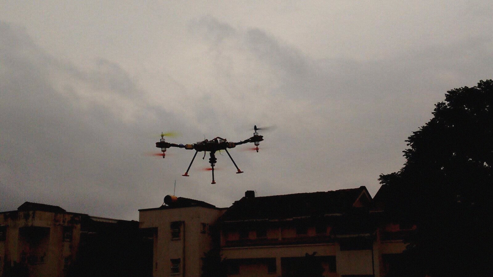
Black against a monsoon sky above the hostel rooftops.
EDF jets
The downloaded-plans folder holds a JA37 Viggen, an X-31, an F-117, and an F-22, all drawn around electric ducted fans. EDFs are hard. The fan is small, so disc loading is high and thrust comes from throwing a thin stream of air backward very fast. For a 64 mm fan making 700 g of thrust, the air has to leave at about 40 m/s, which takes around 300 W once real-world fan efficiency is counted. On 3S that’s 27 A, a 20C discharge from a 1,300 mAh pack. The LiPo packs that survive it cost more than an entire foam trainer, and a hand launch has to reach flying speed on the first try, because a ducted fan at half throttle makes almost no thrust. We built our jets anyway:
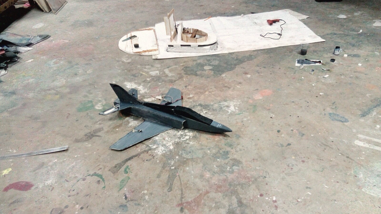
Grey paint hides a lot of hot glue. That one shared the floor with the hovercraft, which belongs to another story.
We learned a few things specific to EDFs. Datasheet thrust was optimistic by about half, and the 1.5x power margin we budgeted evaporated where the forums say 2x. On an airframe this small the glue is a component, so hot glue lost its job to lighter adhesives. The inlet lip mattered more than any of us expected, because a ducted fan breathes through a hole whose smoothness decides how much of the theory survives. A sharp inlet edge makes the flow separate, the fan sees turbulent air, and thrust drops noticeably. The first EDF plane never flew. One consolation: a crashing EDF jet hits things with foam, while an open propeller can cut you.
Some designs stayed digital:
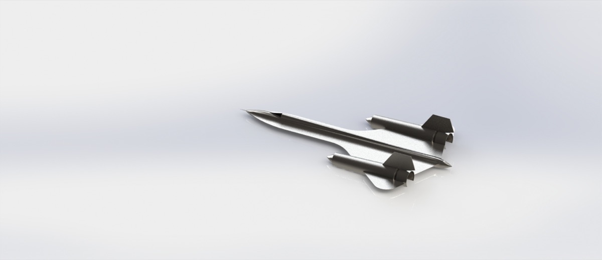
That SR-71 body taught us surface modeling and never flew. There’s a version of this hobby that lives entirely in CAD, and it’s cheaper.
The rocket
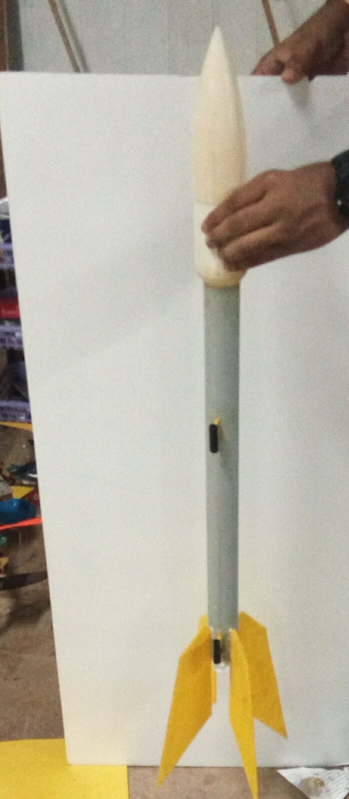
We also built a small model rocket and named it Cohero. A rocket has the same stability requirement as a plane with nothing else in the way. It flies straight only while the center of pressure sits behind the center of gravity, which is the relationship an airplane hides inside its wing position. OpenRocket computes the centre of pressure from the nose and fin geometry, and the rule of thumb is at least one body diameter of separation between the two. We had 1.4. The nose cone came off the 3D printer, the fins came from the same foam stock as everything else, and the swing test (the whole vehicle spun on a string to check that it weathervanes into the airflow) stood in for a wind tunnel we didn’t have. The dimensions went through OpenRocket and RockSim first, because fin and nose numbers are sensitive enough that we wanted two simulators to agree. Both put apogee near 150 m on the motor we planned.
The motor is the dangerous part. Amateur rocketry’s standard propellant is rocket candy, potassium nitrate and sugar in about a 65:35 ratio by mass, melted together and cast into a paper casing with a central core. It’s a weak propellant next to a commercial solid, and the motor we cast was in C-class territory, around 10 N·s of total impulse. Nobody sensible stands next to one at ignition, so the igniter fires electrically from a distance through a circuit we built ourselves, off a launch pad with an adjustable angle.
Theory we read
The other half of the archive is theory we downloaded and half understood: the XFLR5 documentation on vortex lattice analysis, stability derivatives and polars, a University of Minnesota UAV lab paper on extracting aerodynamic models, and a stack of composites guides (resin infusion, carbon layup) collected for a solar UAV that never left its folder. The half we did understand kept showing up on the field. That’s the best argument I know for reading past your level.
What we learned
- The balance point matters more than the airfoil, the motor, and the paint combined. A 10% static margin, a quarter-chord balance on two fingertips, is the only preflight check that matters.
- Datasheet thrust is optimistic. Halve it for a duct, keep the 2x power margin the forums recommend, and weigh the glue, because on a small airframe the adhesive is a component.
- Balance the propeller before tuning the controller. A prop at 8,000 rpm is a 133 Hz vibration, the IMU reads it as motion, and no PID gain can tell a bent prop from a gust.
- Ten cheap airframes taught us more than one careful one would have. Crashes are cheap when the airframe cost twenty rupees.
- Crashes settle design arguments. Every wreck traced to one specific cause, and the repair bench was the only review meeting nobody skipped.
- When the autopilot flies better than you do, that’s useful information. Use it.
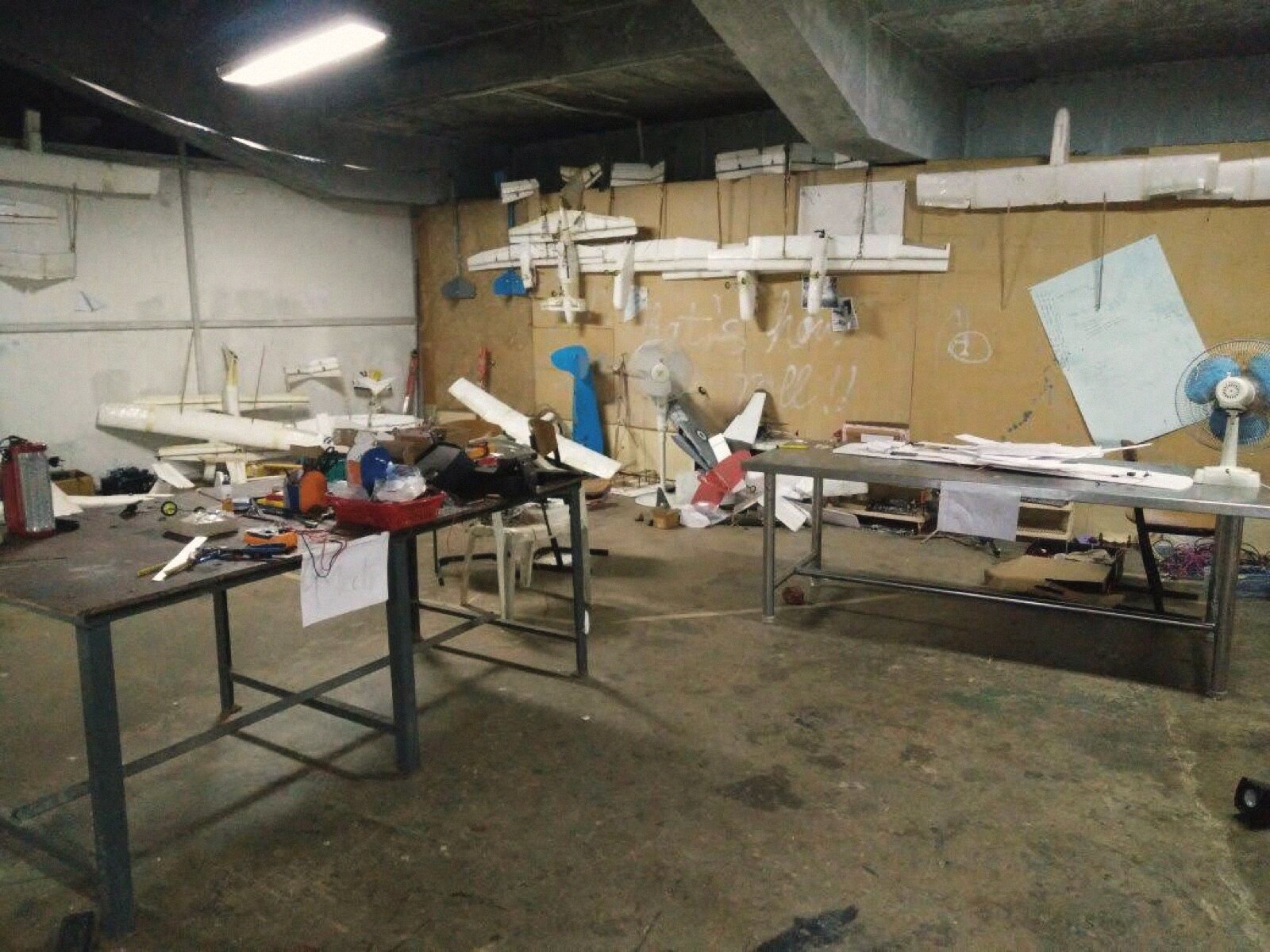
By the end, the wall was full of finished airframes, most of which had crashed at least once and all of which we kept.
The receivers, the ESCs, the LiPo chargers, and the printed-propeller habit all moved straight into the submarine. Different fluid, same lessons.
An April afternoon this month, a hover check on the court outside the workshop.